
|
|
#1
 13-07-2009, 18:11
|
|||
|
|||
|
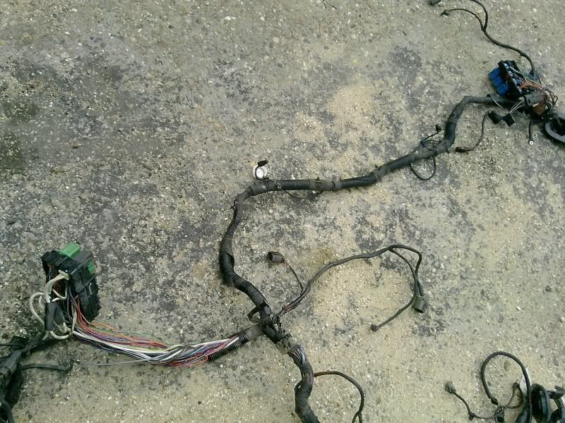
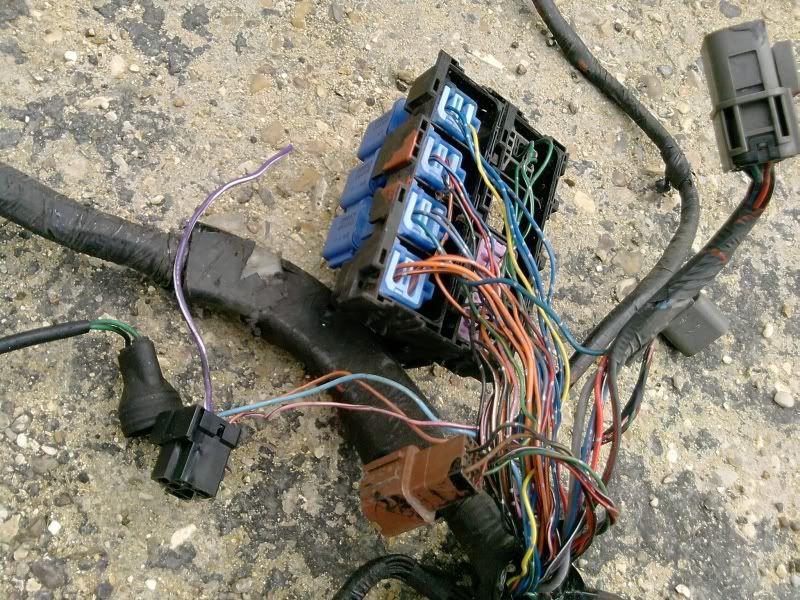
Been looking at my harness today to work out what goes were. I know the How-to gives a list of what wires attach to what but it doesnt state were the wires are from/which plug on the loom. And what about the wires that are left, are these redundant ie to be taped off? If someone could give me the heads up please...
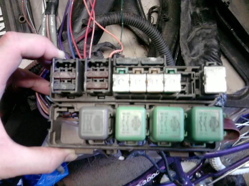
On club-s12, some owners are now saying no relays have to be wired in apart from the re-wired fuel pump 1st picture two plugs Grey 8 pin plug with 7 wires 2nd picture the white plug by the ecu plug 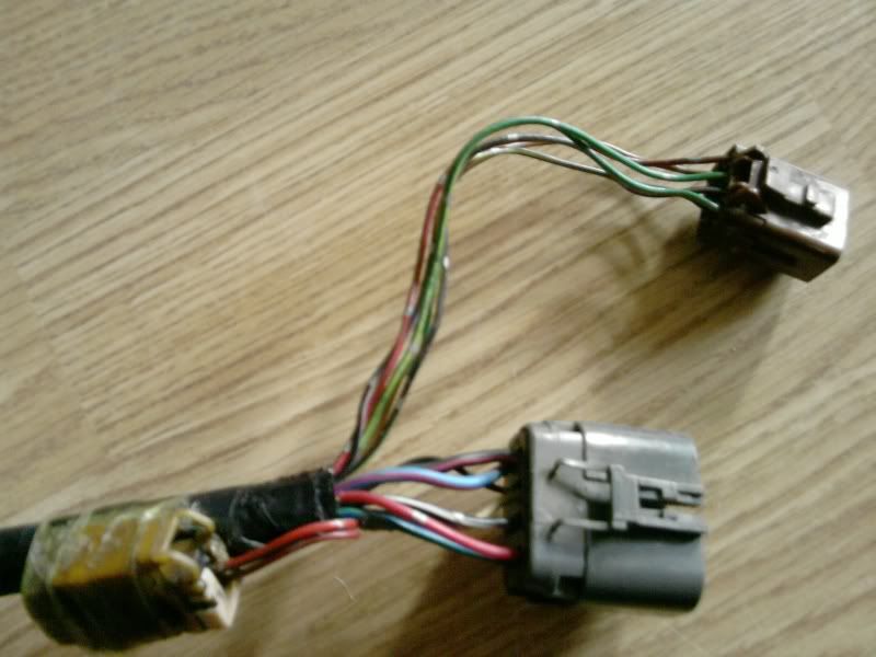 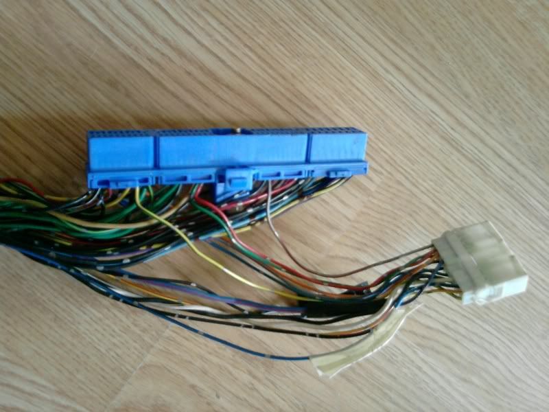
__________________

|
|
#2
13-07-2009, 22:55
|
||||
|
||||
|
if no ones answered this before i get home in a couple of days il get some pics and details up of one of my converted looms
__________________
 Quote:
|
|
#3
14-07-2009, 00:45
|
||||
|
||||
|
Looks like all you have is the engine harness. I took the power harness out of the S13 too which contains the 3 relays and it plugs in to the engine harness.
If you still have access to the S13 to rob it from it's worth using. All you then have is permanant live, igntion live, an earth to get the engine running. You could run the whole lot off one relay or just have the relay run the fuel pump but then your subjecting more current demand through the ignition switch of the car which otherwise would just switch on relays with less than an amp being drawn, compared to many more amps the other way.
__________________

|
|
#4
14-07-2009, 09:38
|
|||
|
|||
|
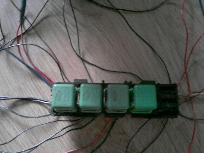
After checking and I found the loom that came with the Det engine I got had been hacked. I did however get another full loom which basically covered the whole of the engine. I have found the Relay box from the offside (3 green relays) were the loom goes round the engine bay to the nearside were there is another Relay box. At this end I can see the Brown/Grey connectors you are talking about
__________________
Last edited by northerner; 14-07-2009 at 10:50.
|
|
#5
14-07-2009, 10:54
|
|||
|
|||
|
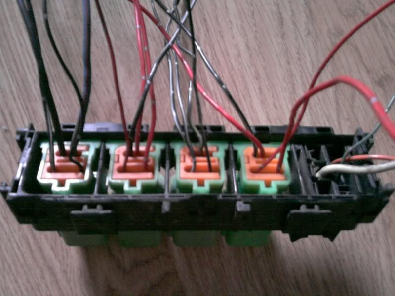
Are you saying I need to strip the Three relays/wires out from the loom all the way to the brown/grey connectors??? If so, I see from the relay box on the Nearside that at least One Blue wire goes into a Blue relay from the Grey connector? Is this going to cause problems when cut or is it just spliced back in ???

__________________
|
|
#6
14-07-2009, 11:05
|
||||
|
||||
|
Yeah I remove from that loom the wires I didn't need. I can't remember what the blue relay was for, but I chucked it out.
You'll end up with a number of black and red wires that feed the relays and the loom for you to put permanent and switched power to. There's also one very thin black wire that needs to be earthed.
__________________
|
|
#7
14-07-2009, 20:50
|
|||
|
|||
|
Quote:
__________________
|
|
#8
14-07-2009, 21:19
|
|||
|
|||
|
I also followed the ECU pin diagram to find out for sure what each wire does on the brown and gray plugs. This is what I found
8 Pin grey plug : Red/Silver band ECU 12v perm live PIN 58 Blue/Green silver band A/C relay *NOT USED* Black/White silver band ECU eccs 12v switched PIN 109 Blue/Red Plug loom 12v switched (no pin) Black/Red Ign power 12v switched PIN 45 White (shielded) Knock sensor (I will wire this in further towards the bulkhead) 8 Pin brown plug Green/Yellow silver band A/C relay *NOT USED* Black/Red silver band Eccs power 12v switched PIN 16 Green/Orange silver band Inhibitor relay *NOT USED* Black/Purple Fuel pump relay PIN 18 (NOT SURE WHICH PIN ON THE FUEL PUMP RELAY) Black/Yellow ***** Dont know what this is ???!!**** Brown/silver band O2 heater (my ECU plug does not have an 02 wire) Now I think I have all these correct (if not then say!) but I need to know if my dodgy relay wiring is OK ? Can I run one Permanent Live/One switched 12v/One ground jumped through all the relays ??? 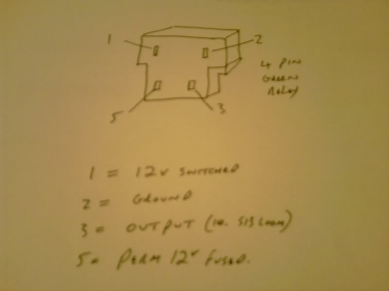
__________________
|
|
#9
14-07-2009, 21:58
|
||||
|
||||
|
I recall that some of the relays shared the shame power source even on the standard loom. You only need 3 relays though not 4.
I'd have to look back at my loom to remind myself what I did, but basically the 3 green relays plug in to the engine loom via the brown and grey plugs. You'll find the length of the wiring quite long, you could shorten these if you wanted. I then found there were loose wires going to the relays for power, earth and switched ignition.
__________________
|
|
#10
14-07-2009, 22:03
|
|||
|
|||
|
Once I'm ready for the transplant and the DET is in, I will shorten the wires accordingly. The 4th relay I put in there is for the Fuel pump or are you saying I could double it up on another ?
__________________
|
 |
|
|


 Linear Mode

