
|
|
#51
 04-12-2008, 16:18
|
||||
|
||||
|
the igniter doesnt connect 2 my ca18det engine-ecu loom but its placed on a separate wirng loom that goes 2 the s13 chassis loom and runs 2 the green relais. I thougt i had a foulty wiring loom but its complete and isnt cut nowhere, 30PSI told me to wire it 2 the relais box with the 3 green relais,Im trying to do that but still trying 2 figure out how to do it correctly
__________________
87 silvia (ca18det) 94 Alfa Romeo 155 2.0 8v ts (daily driver)(planning Lancia Delta swap) 84 silvia (ca18et oldtimer) Turbolag is nothing but foreplay Last edited by sjef200sxTurbo; 14-12-2008 at 14:26. 
|
|
#52
06-12-2008, 15:45
|
||||
|
||||
|
Ive just found out thru the US site that europen left hand drives (I live in holland) Have that igniter and connected thru the main car harness instead of having a separate loom that connects to the engine harness.
Im thinking of ordering an loom from the UK, does annyone have a conplete DET harness left?
__________________
87 silvia (ca18det) 94 Alfa Romeo 155 2.0 8v ts (daily driver)(planning Lancia Delta swap) 84 silvia (ca18et oldtimer) Turbolag is nothing but foreplay Last edited by sjef200sxTurbo; 07-12-2008 at 13:42. Reason: I made a mistake
|
|
#53
30-05-2011, 20:50
|
||||
|
||||
|
Here I have the Instrument panel out
 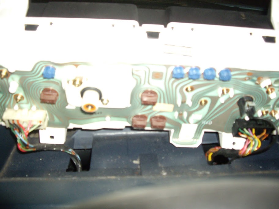 Which wire would I splice into to get the Rev counter working? 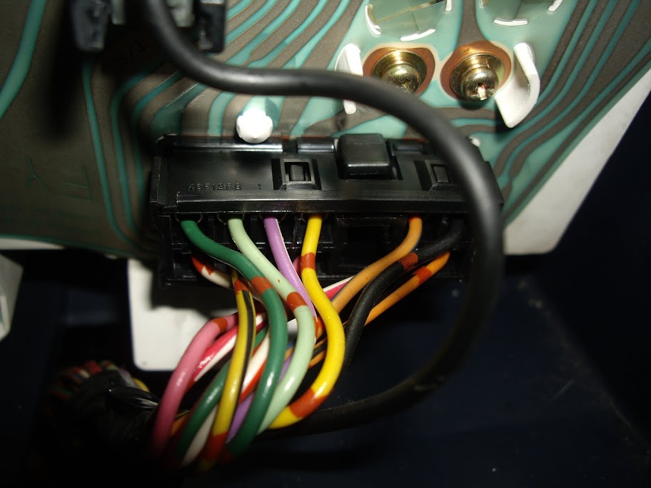 Which wire is it I splice into at the Coil Pack side 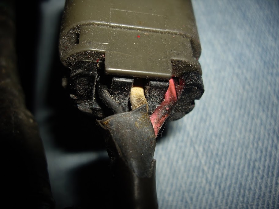 Is the blue black wire on the white block near the ECU the Temp Gauge wire? Should this be cut and extended to the ECU? Which PIN would it connect to in order to get the Temp Gauge working? 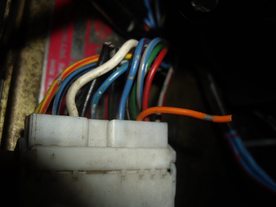 I'd like to thank Pukka for sorting this project out and getting it running just a few more jobs which my budget wouldn't run to with Jon, a bit of tidying and were ready for the shows this summer. Last edited by paulsilv; 30-05-2011 at 21:06.
|
|
#54
31-05-2011, 23:25
|
||||
|
||||
|
Think I've found the info I need if someone can confirm I am right.
TACHO the 4 wires from the ignitor that go to the coilpacks are the ones you splice 4 diodes onto then join the "cathode" (striped) ends together and join them to one wire which you run to your tacho. There is a light green wire at the back of the tacho, which you cut and join to this wire. You have to remove the instrument panel to get at the connector that has the light green wire in it. in the pics above there is a light green wire on both plugs into the back of the instrument panel, is it the one on the right as you look at it? The stripe on the Diodes is towards the tacho, as the current will only flow in that direction. Someone on Club S12 has spliced in to the tach gauge signal wire, which is part of the S12 primary transistor wiring harness, down near the maf location. Where is this and which wire is it? TEMP GAUGE Find the blue/ black wire from the small white s13 plug. connect a wire to it, and run it up behind the instrument cluster. Next snip the purple/ white wire behind the cluster, which is the temp gauge signal wire, and connect the wire that you ran up to the cluster side of the purple/ white wire. Last edited by paulsilv; 31-05-2011 at 23:39.
|
|
#55
01-06-2011, 00:33
|
||||
|
||||
|
I did it by tapping in to each ground wire that went to each coil and collated them together via the diodes to have the combined signal. Instead of tapping this in to the back of the instrument panel I used the original signal wire from the earth of the original coil. This was on a Datsun by the way but the principal should still be the same. On the S12 I think its the blue wire going to the coil that feeds the instrument, but check.
__________________

|
|
#56
05-06-2011, 17:49
|
||||
|
||||
|
Got the Temp Gauge wired in and working like a dream
 But I am stuck on the Tacho wiring. Wired the 4 Diodes together with the stripe toward the Tacho  An here again from slightly further away showing the 4 seperate wires to be spliced into the coil packs  This is the plug that plugs into the Ignitor with 4 wires coming off it Fig 1.  If you follow these wires through the loom they eventually end up at this plug. You can see them entering on the left hand side Fig 2.  And again the same plug closer up Fig 3. 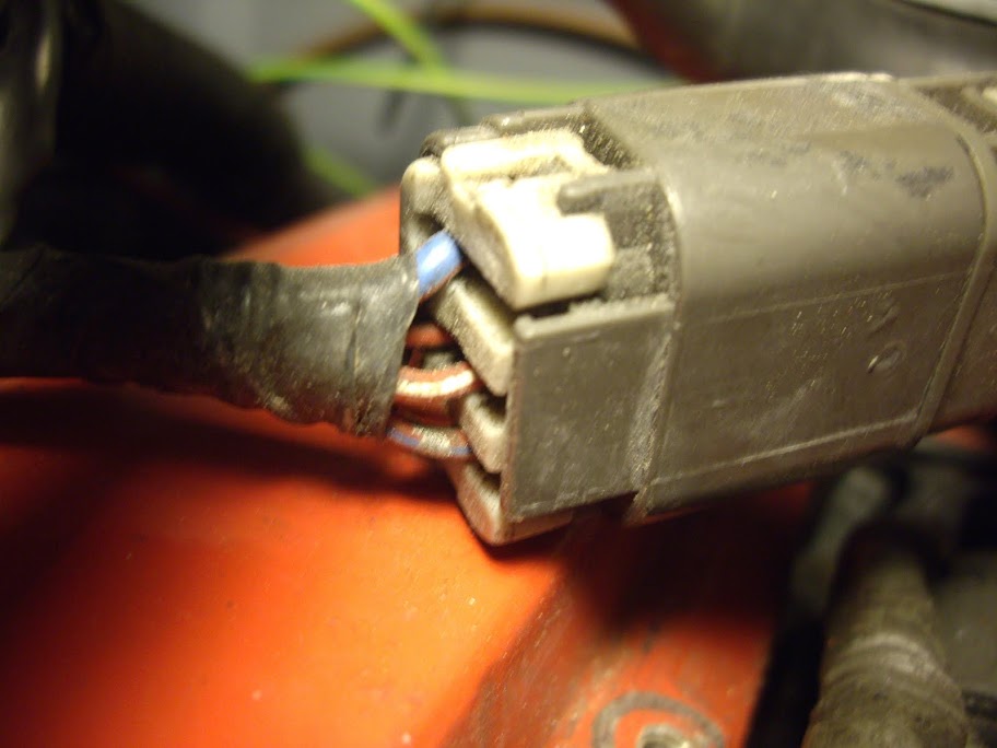 These wires then come out of the other side of the plug in different colours (As Below) Which are the correct ones to splice into???? Fig 4. 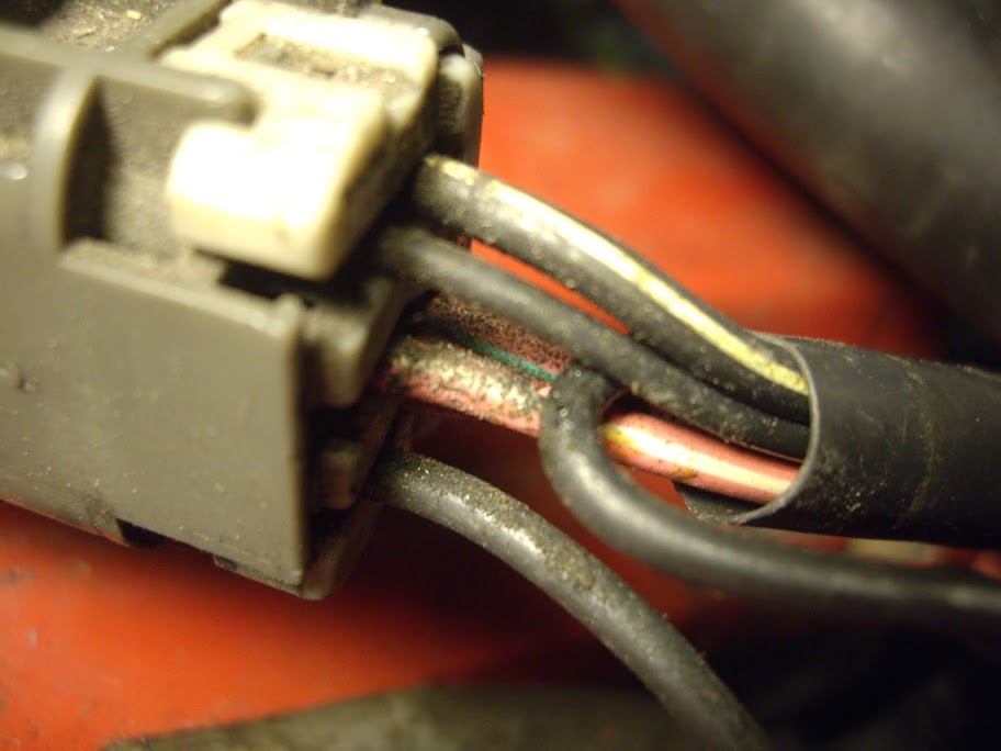 I am completely lost trying to find the original blue signal wire from the original coil. Do I cut and join or Splice ??? Where is this??? If I dont use this original blue signal wire, is it the light green wire I should be using behind Tacho??? . Last edited by paulsilv; 05-06-2011 at 18:21.
|
|
#57
23-06-2011, 17:48
|
||||
|
||||
|
Sorted the Rev counter, worked like a dream.
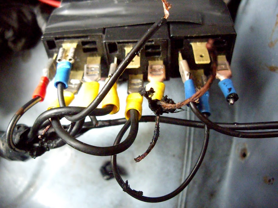
Started tidying the wiring up, moved the relays about 4 inches, one of the spades connectors came off and started to fizz the loom. Now back to square one. Not suffering the cost of sending it off again. Any help would be gratefully appreciated will post a pic of the relays for any info on wiring new ones back in. 
|
 |
|
|


 Linear Mode

